| Home | Newsletter | Locations | Diary |
|
Indexes |
|
|
|
|
Article Pinhole Kit Mk 3
If Pinhole cameras are new to you, see
pinhole cameras
The first experiments I did with pinhole photography on a DSLR simply involved black card, with a pin pushed through it, and this produced an image. To many it was magical, some thinking I had pulled some conjuring trick on them. The second stage was to make up a series of experiments using a small foil patch with a pinhole in it and placed over card, this is what you see in a number of the articles we have on this site, including:- The quality is better, yet its still something that most photographers can do with little more than household items in a few minutes. This is an art form, every lens and camera arrangement you make is different, even used two days, on occasions a few minutes apart can be different. The kit we developed in order to show people pinhole photography at this stage involved a lot of wraps with foil on and only one of these had a door system that allowed two different photos from the same arrangement without changing tubes, lighting or position. As using this was an artistic experiment, results were not reproducible. The 3rd stage, was to develop the idea that we could create one gadget, that could:-
So I talked to an engineering company about producing something, and this discussion continues and you may see this turn into something that can be bought rather than made. At the same time I wanted to develop the idea and prove the concepts and I wanted at least one form that could carry on as before and be created by most photographers. However to achieve so much in one gadget, I
had to make changes, firstly to swap the foil to something that was more
predictable, and after some search, looking at several pinholes that could
be purchased, I selected some produced by the Pinhole Factory, there is
another article specifically looking at these pinholes - see
Pinholes from the
Pinhole
Factory.
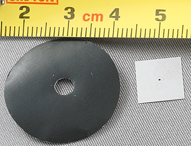
0.4mm Pinhole on right, retaining ring on left, both far larger than life The second change was that in order to have a sliding mechanism, so that I could move the position of the pinholes, as well as change them, I needed to use something more substantial than the lightweight card I had used up to now, and like many photographers I have mountboard, used to mount photos in frames, and a mountboard cutter. I have used this for the base and for the sliding mechanism. When this is used to mount a photo you usually cut at 45 degrees so as to give a fine line created by the centre of the card being a different colour. One of the blades on the cutter is at this angle. I have used this to cut two slides, using the card the opposite way up to normal for the sliding rails, and the usual way up to produce the slide that will slide within it. I don't have a computerised mountboard cutter, but if I had this would be a far simpler task, so I will have to see if one of those who have one could cut out a kit that would simplify this process for others. Most mountboard has a coloured surface and the centre is a different colour and back plain, but we had some solid black mountboard in stock that is black, front and back and right through it's core, and this is what I decided to use. The weakness in the design is that I still have this fixed to a thin card wrap, and using elastic bands to put it in place. I looked at a Nikon body cap, and considered making it smaller, cutting a slot in the body cap, and in some ways this would make a better job, but I was not confident that I could do this successfully, and also felt that many others would have similar problems, and I wanted this to be a project that many photographers could handle. I also thought that some would be reluctant to destroy their cameras body cap. So we still need to look to the engineers solution that will give us a smaller, easier to click, on and off solution. The design is
shown in a PDF file that you can print out by
clicking here
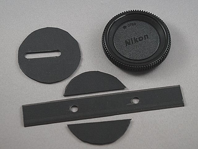
The parts that you end up with out of the mountboard are:-
Parts cut out, a Nikon body cap is also shown top right In addition to this you need:-
or you could cut a slit in a body cap that you glue this to and mount it this way.
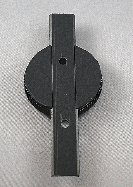
I put these pieces together by using a staple gun to hold the flanges exactly where I wanted them, and hammering the staples down tight, the card wrap was then glued on, the staples holes might not be light tight, but they are under the wrap. I could have glued it all, and not used the staples. I marked where the centre is likely to be and the sliders when they are in the central position. I fitted the pinholes having trimmed the retaining sticky rings so that they did not go wider than my sliders, and labelled the sliders with the size of the pin holes.
Using this kit The individual slides each contain a different sized pinhole, in theory when a longer distance exists between the sensor and the pinhole we should be using a larger pinhole, as this is, in effect, the focal length of this pinhole lens. The slide allows them to be moved to any position, from slightly below central to a high point, but you can go in any direction, allowing perspective control on different axis and in different amounts to be explored. Used side ways for example, you can take a photograph into a mirror without your reflection or the cameras being present. By using it with the tubes, we have 7 combinations of distance/focal length.
See Also:
Pinholes from the
Pinhole
Factory
Pinhole
Cameras
- Further Information
Stanton Drew Stone Circle - Pinhole
Gallery
|
||||||
|
||||||
| . | ||||||
|
||||||
|
|